GPU Simulation
I know I said I was going to do a multi-part series on the “Borderland between Rendering and Editor” and I’m still planning to do so, but over the last 2.5 weeks, I’ve been working on something else that I feel is worth writing about while it’s still fresh in my head. In the latest release of The Machinery beta (2020.4), we introduced a way to setup and author various types of GPU Simulations using Creation Graphs.
Back in December 2018, I talked about “The Anti-Feature dream”, the idea is that instead of building complete features and expose them directly to the user we should be focusing on breaking down the features into reusable building blocks and expose those instead. We then assemble those building blocks at a higher level (often in data) to create the complete feature. This is a development strategy we deploy pretty much everywhere in The Machinery code base, the GPU Simulation system is no exception.
So while the initial development focus has been to get the building blocks in place to be able to create particle systems, you can already use it for doing any kind of arbitrary buffer processing reaching way beyond simple particles.
In today’s post, I will try to give you a high-level overview of this new system, primarily targeting Technical Artists with the hope to spark their interest in toying around with it.
Core nodes
The main building blocks for setting up a GPU Simulation circulates around the *GPUSim* -nodes
found under the Simulation/ category when editing a Creation Graph.
There are three core nodes:
GPUSim - Init
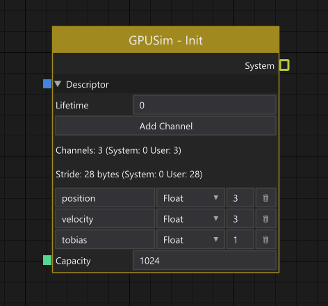
Init node.
The responsibility of the GPUSim - Init-node is to set up a new simulation. A simulation operates
on a number of elements, where each element is defined by a set of user-defined channels.
Channels can be freely named and typed to anything that makes sense for the specific type of effect
you are building.
In addition to defining the different channels, you also decide if the elements should have a
maximum lifetime after which they are automatically recycled, or if the spawned elements should live
forever (lifetime = 0). If the lifetime is set to anything greater than 0 an implicit “system”
-channel called time is automatically added.
Lastly, you need to set the capacity of the system, i.e specify the maximum number of elements that can be alive simultaneously in the system. The total memory requirement of your system then becomes capacity * stride bytes.
The output of the node is a System, which is what all of the other nodes operate on.
GPUSim - Spawn
Spawn node.
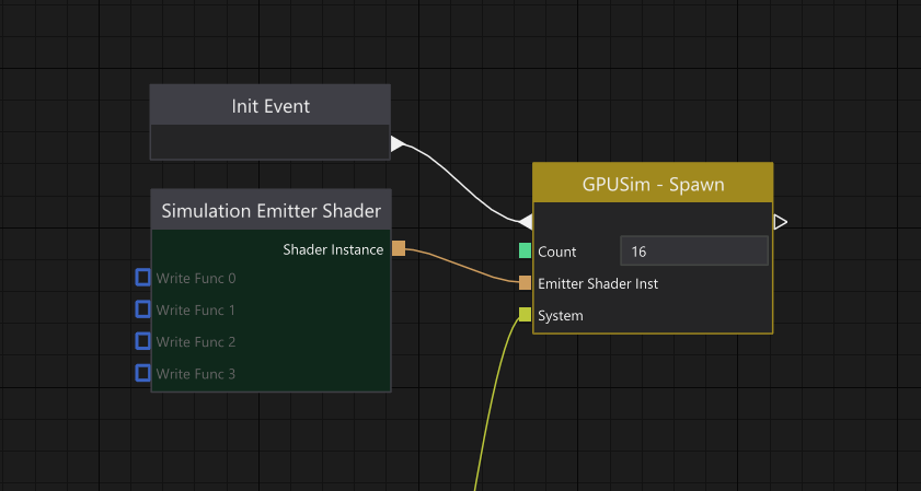
When the setup of a simulation is done, using the GPUSim - Init node, it’s time to inject some
elements into the simulation. This is done using the GPUSim - Spawn node. It runs when it’s
triggered by an Event. In this case, I’ve just hooked up the “Init Event” which is an event that is
automatically triggered by the Render Component after an entity has been loaded.
The number of elements to inject into the simulation is defined by Count. It’s worth noting that
a spawn will never fail unless Count is greater than the Capacity of the system (as specified on
the init-node). The reason for this is that the simulation buffer is treated as a ring-buffer on the
engine side, so if the simulation buffer can’t fit the spawn operation it will overwrite the oldest
n elements in the buffer.
Exactly what the channels of the spawned elements are initialized to is controlled by a compute
shader. In this case, I’ve just hooked up the default “Simulation Emitter Shader”. In itself, it
won’t do anything (except initialize the element time to 0 if the system has a Lifetime specified
to anything other than zero on the init node), unless you hook something up to at least one of the
Write Func connectors. We will take a closer look at how this works later in this post.
It might also be worth mentioning that the reason for why the background color of the “Simulation Emitter Shader” node is tinted dark green is to indicate that it’s a node that will execute entirely on the GPU, as it will compile into a shader program.
GPUSim - Update
Update node.
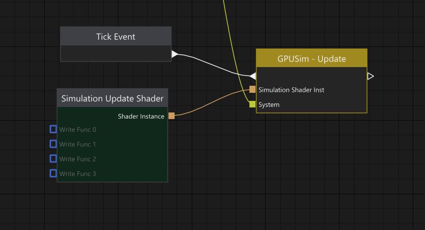
Once we have a number of elements injected into the system, we typically want to update them in one
way or another. This is done using the GPUSim - Update node. Just as with the spawn node, it runs
when it’s triggered by an Event, and for most types of effects you will likely be hooking up
something like the “Tick Event” which is an event triggered by the Render Components once per frame.
Again, similar to the spawn node, the update node will update all active elements using a compute
shader. I’ve wired the default “Simulation Update Shader” to it, which in itself doesn’t really do
anything (except advancing the element time with the frame delta-time if the system has a Lifetime
specified to something other than zero on the init node) unless you hook something up to any of its
Write Func connectors.
Additional nodes
So with the three nodes described above, we have a way to set up a new simulation system, inject elements into the simulation and update those elements. That can be viewed as the core nodes of the new GPU Simulation system in The Machinery.
Now, let’s take a look at some more nodes that we need to do some actual work:
GPUSim - Write
Write node.
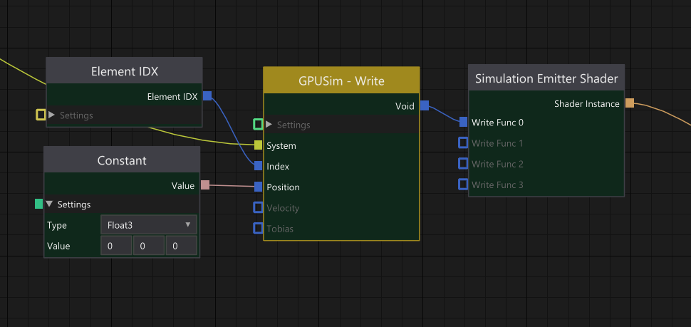
As the name suggests, GPUSim - Write is responsible for writing channel data to the element
pointed to by Index. The inputs Position, Velocity, and Tobias are the three channels we
declared on the GPUSim - Init node. So essentially any connector that appears below Index is
data-driven by the channels declared in the system.
Per default, the index will be translated to be relative to the start (i.e., first active element) of the system, but there’s nothing stopping you from freely indexing any part of the buffer by setting the indexing mode to absolute indexing. Note though that care must be taken to accidentally write to memory that simultaneously might be read from or written to by another “thread”.
GPUSim - Read
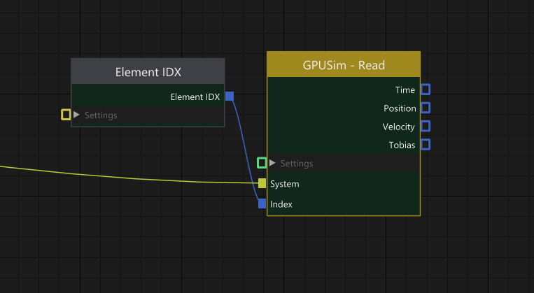
Read node.
Same as GPUSim - Write but for reading the channel data of an element pointed to by Index.
Here you can see there’s also a Time output. This is because the System hooked up to this node
has a Lifetime that is greater than 0 specified on the GPUSim - Init-node. As the time channel
is controlled internally by the system it can never be written to, only read.
The output from Time is a floating-point value holding the normalized elapsed time (0–1) from the point the element was injected into the system by a spawn node.
GPUSim - Draw Command
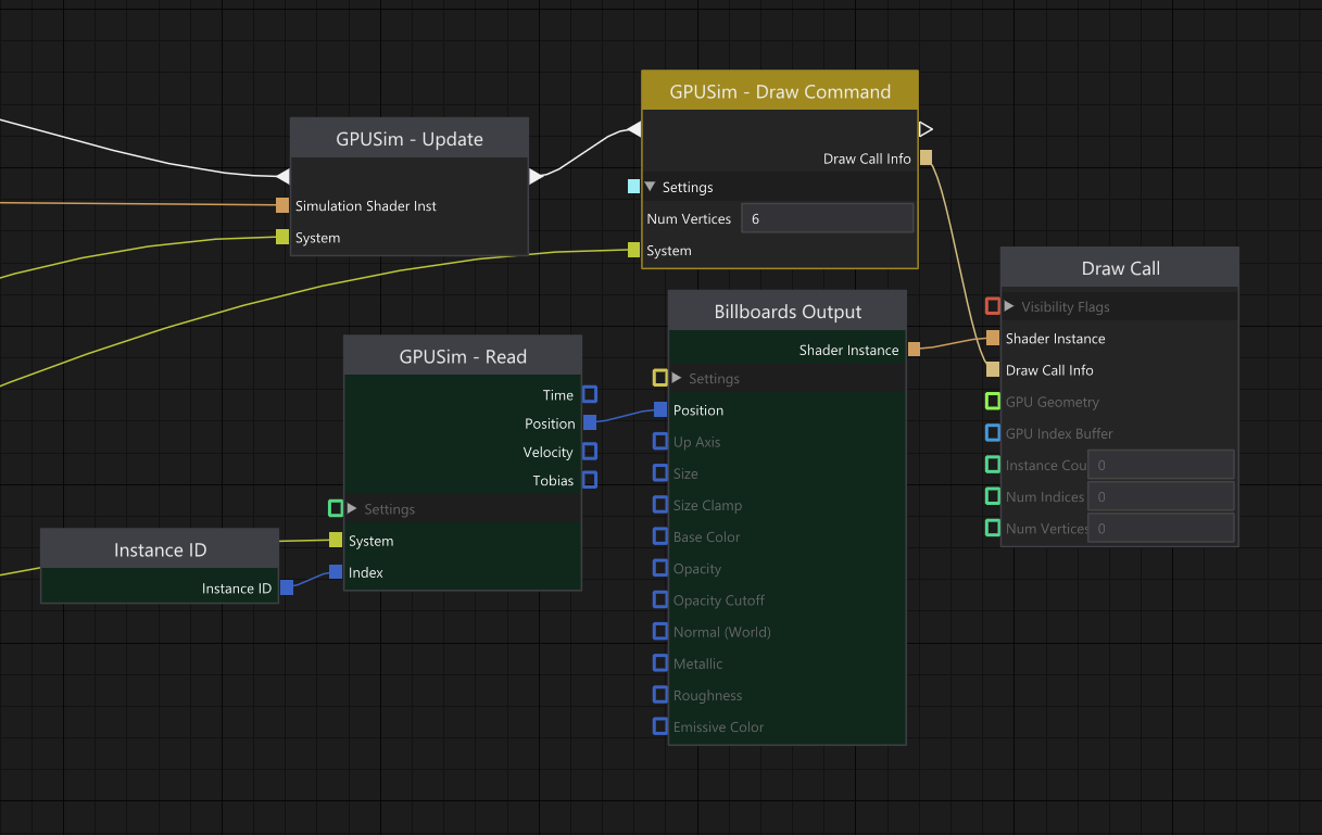
Draw node.
The write and read nodes together with the core nodes give us everything we need to start
authoring particle behaviors. Depending on what kind of effect you are authoring it’s not unlikely
that you want to visualize each element as some kind of draw call instance, this is where the
GPUSim - Draw Command-node comes into play.
Its job is to build a draw call with an instance count that equals the number of elements currently
alive in the system. In the current release of The Machinery, this node is fairly primitive as the
only thing you can specify as input to it is the number of vertices the draw call should contain,
but going forward my intention is to flesh it out with more features, and also expose some way for
shaders authored to procedurally generate their vertices to output it’s desired vertex count. That
way there will be less room for user error (right now there’s an implicit assumption that you know
that the Billboards Output shader executes on 6 vertices per billboard — clearly not ideal from a
user perspective).
Since the system has been designed to be able to simulate massive amounts of elements (hundreds of thousands, or even millions) we don’t want to keep track of element lifetime on the CPU. Even if we were to track the lifetime per spawn (i.e the injection point of a number of new elements into the simulation) there are no guarantees that we won’t end up with a very large number of spawn calls to keep track of. Instead, my current idea is to keep track of lifetime and the number of active elements in the simulation entirely on the GPU and use indirect dispatch and draw calls that read their arguments from GPU buffers.
As I’m still working on this, I’m not 100% sure how well this will work out for us in practice, but I can’t see any reason for it to fail. And as a nice side effect, we’ll also get an efficient way to drive spawning of new elements entirely from the GPU, something that can be very useful when you want to do stuff like spawning new elements into a system when an element of another system collides with something.
Rate Emitter
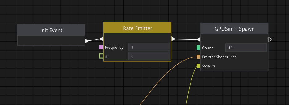
Rate emitter node.
The last node I wanted to touch on is the Rate Emitter. This is a very simple node that is set up
to trigger itself at a certain frequency. Setting the frequency to 1 means that every second the
node will trigger, schedule itself to trigger again in 1 second, and then forward the event to the
GPUSim - Spawn node.
At the moment, this node runs entirely on the CPU, but it’s not unlikely that we will end up deprecating this node eventually. I’ve started thinking that it might be better to just introduce a generic spawn event buffer associated with the system. This spawn event buffer could then be populated either from a node similar to this one or from another system requesting a spawn.
Wrap up
Let’s put all of the above nodes together and create a simple particle effect:
A few frames exported as a gif animation.
The Creation Graph for creating the above effect looks like this at the moment:
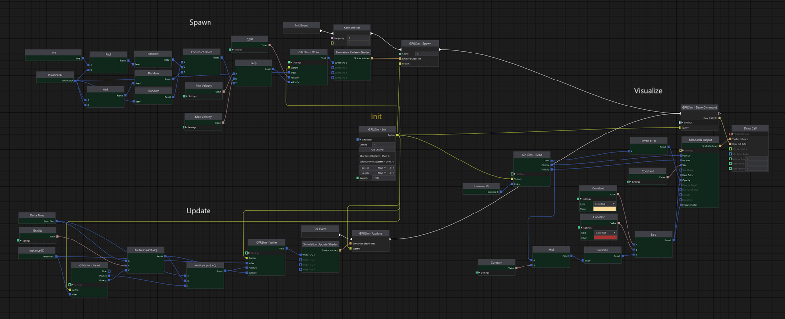
Creation graph for particle effect.
In the middle, you have the initialization of the system. On the upper left side, you have the spawn which basically just randomizes a velocity for each element. On the lower left side, you see the update code which basically just integrates the velocity with the gravity and then integrates the position with the velocity.
Last, but not least, you have the visualization part on the right side. Each element is rendered as a billboard. The billboards are locked to face the camera but only allowed to rotate around the velocity vector (read from the element). The color is just a lerp between yellow and red using the normalized time of the element as t.
This might look a bit overwhelming to some, but as you can see, most of the nodes are tinted dark green, meaning that they are simply just generating a snippet of HLSL-code. Over time I think we and our users will create lots of small helper nodes that significantly will reduce the overall number of nodes needed, so right now I don’t see it as a big problem.
What I’m a bit more worried about though, is that it feels somewhat hard to organize the graph in a
nice way, I’d like to somehow make it clearer which parts of the graph that belong to a specific
“stage” (spawn, update, visualize). Also, I find it kind of painful to drag out all the system
wires (all the yellow wires going from the GPUSim - Init node in the middle). If you are a reader
with experience in similar systems and feel you have good ideas on how to improve the workflow —
don’t hesitate to reach out.
That’s it for this time. If you haven’t already, sign up for our closed beta and try it out yourself. We’d love to hear your thoughts and get feedback.