Supporting Native HDR Monitors
Monitors that can display HDR color spaces are not very common on gaming PCs. Nevertheless, I bought one when creating my workstation in order to add support for fancy things like 12-bit color depth and HDR10 output. I never actually implemented this during university, but during my internship at Our Machinery, I took the opportunity during several “Fun Fridays” to add support. This blog post details how the implementation works on a theoretical level, the practical aspects of the implementation, and the problems I ran into.
Human color perception
Humans can only see a small part of the electromagnetic spectrum (380nm to 760nm) and we don’t even view that uniformly. Instead, our eyes have cone cells that react to different wavelengths of light to produce the perception of color. We have three types of them: short (S), medium (M), and long (L). These don’t map to specific colors, but instead, they each respond to a range of colors:

Response of each cone cell type to different wavelengths of light. Picture from Wikipedia.
Notice how the green wavelengths have the most overlap with all cones. This means that we can see more shades of green than any other color. One other property of human vision that is useful to know is that we perceive brightness differently than it is mathematically. We’re better at seeing differences in darker colors than in bright colors. This relationship roughly follows a power curve. Human vision is more complex than this, but this is all we need to know for now.
Standardization of color
When trying to support any hardware feature, it’s always nice to work with some sort of standard. Color is no different, and has been somewhat standardized since 1931. Most people are familiar with sRGB colors, but the sRGB color space only covers a subset of the colors that the human eye can see. To be able to compare different color spaces, it is useful to have a reference space that is big enough to encompass the full range of human perception. For this, we turn to the CIE-XYZ color space and the accompanying CIE-xyY space.
CIE-XYZ (Commission Internationale de l’éclairage XYZ) is a color space designed to capture the entire visible light spectrum in a linear space. This has the advantage that it’s easier to do math in this color space as multiplying any color by two will double its brightness. This color space is however a bit abstract. Y stands for luminance, which is a very useful property, Z is quasi-equal to blue, which is a bit hard to reason about, and X is a mix of the three CIE-RGB curves, which is even less helpful to reason about. Therefore we generally don’t visualize this space directly but instead convert it into CIE-xyY space.
We are typically interested in visualizing chromaticity when using the CIE-xyY color space. Therefore the main two components (x and y) which represent normalized chromaticity are visualized, whilst luminance (Y) is set to a fixed value for the entire image.
Converting from CIE-XYZ to CIE-xyY is easy enough:
tm_vec3_t cie_xyz_to_cie_xyy(tm_vec3_t color)
{
    float x = color.x / (color.x + color.y + color.z);
    float y = color.y;
    float z = color.z / (color.x + color.y + color.z);
    return (tm_vec3_t) { x, y, z };
}
If we set luminance (Y) to a constant value, we can plot the x and y on a normalized graph to show the gamut of human vision. This is the common background used to compare the color gamuts of different color spaces and is known as the CIE-1931 chromaticity diagram.
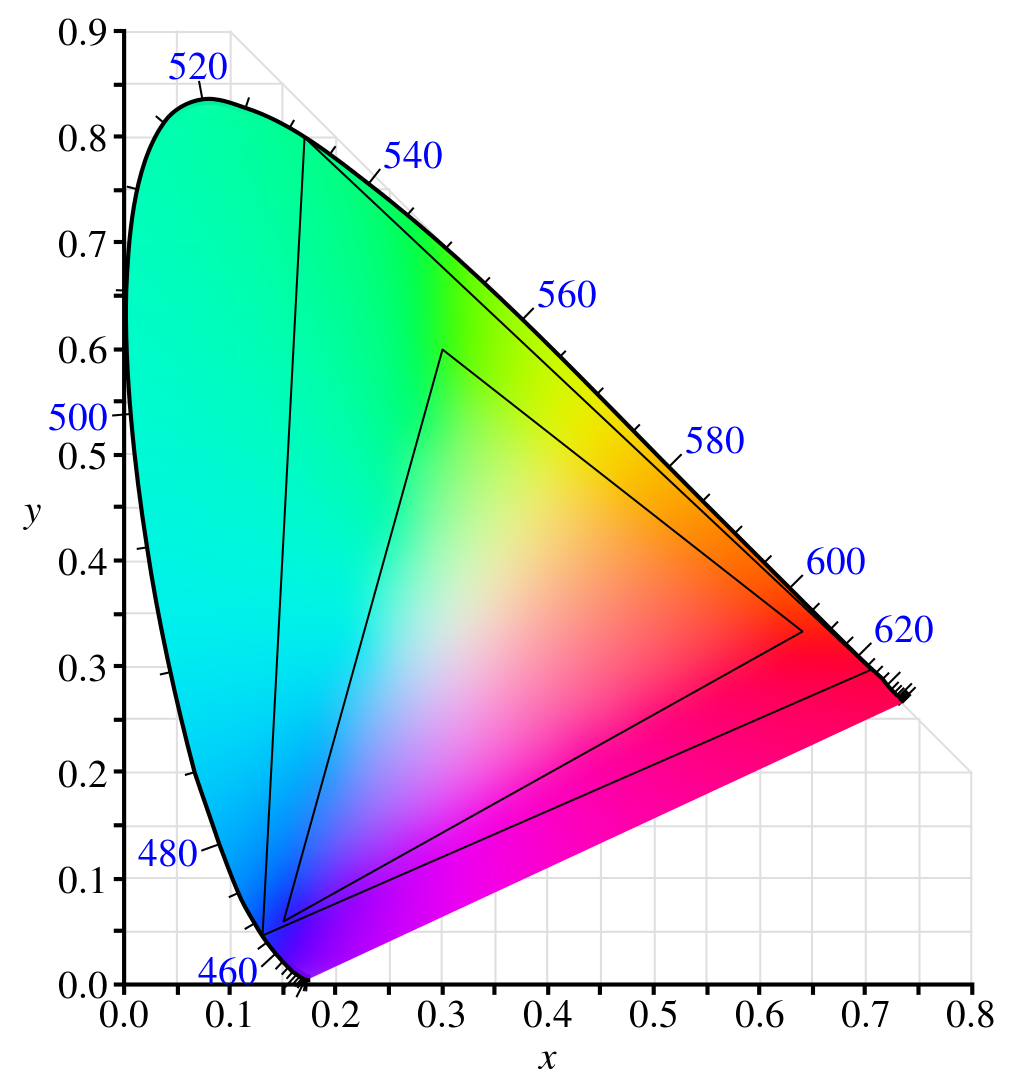
The human vision gamut.
In this diagram, I’ve visualized two color primaries. The small triangle is BT.709 and the larger one is BT.2020. Note that neither of them fully encompasses the entire visible light spectrum, but BT.2020 has a much wider gamut. If you want to know more about the CIE-XYZ color space; I recommend watching: “RGB to XYZ: The Science and History of Color" by John Austin.
Color primaries
Color primaries define the pure colors in a given color model, i.e. what is meant by pure red, green, and blue for a given color space. It also defines the color space’s white point, which is the pure white color of the color space. These color primaries are defined using the coordinates of the 3 corners of the color gamut in the CIE-xyY color space and are generally a subset of the visible color spectrum, but not always. A few common color primaries are:
- BT.709 (Rec.709), the most common one. This is often just referred to as sRGB and is the standard for HDTV.
- AdobeRGB. This has a wider gamut than BT.709 and was developed by Adobe to encompass most colors available on printers.
- BT.2020 (Rec.2020). This is the standard for UHD TV, often just referred to as HDR10. Note that this requires 10-bit color depth.
- ACES (AP0). This was created by various industry professionals under the auspices of the Academy of Motion Picture Arts and Sciences. It encompasses the entire visible color gamut and also requires 10-bit color depth.
BT.709 is supported everywhere so we traditionally use it in games. BT.2020 is supported by some monitors (emulated or natively), but not many games actually support it. This is the one we’ll be focusing on.
Note that it’s not useful to support wider gamuts on monitors without at least 10-bit color depth because when you display a color gradient with too few bits you get banding:
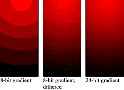
Banding of color values on low bit depths. In the left two images, only 3 bits are used for the red channel. In the right image, 8 bits are used.
This example is rather extreme, but things like this can easily happen when rendering in an HDR space without deep color support.
Transfer functions
Remember that we can distinguish darker colors better than brighter ones? This is where transfer functions come in. The original sRGB transfer function was used for CRT monitors to compensate for its input-output characteristics, but nowadays we use them for better color encoding. This is because the power curve of the transfer function will dedicate more bits to the darker shades. The transfer function is often called “gamma correction" and is different depending on the color space. Often times, the combination of color primaries and a transfer function is referred to as a color space. To give a few examples:
- BT.709 is often coupled with the sRGB transfer function in order to create the sRGB color space. This is how most game engines define their LDR color output space. Instead of the official sRGB transfer function, a power curve of 2.2 was often used as an approximation.
- BT.2020 is often coupled with either the ST2084 PQ or HLG transfer function. The most common one is ST2084 PQ.
- AdobeRGB has its own transfer function, also called AdobeRGB for clarity :)
The Machinery solution
Most HDR solutions I’ve come across support only one or two HDR standards. This didn’t seem very flexible to me, especially since Vulkan supports a wide range of color spaces. I wanted to support at least all of those. I decided to stick close to the Khronos color space definition which defines a color space with the three parameters discussed earlier. I also added two extra fields that help with picking the right color space implementation.
// Defines how to interpret decoded numerical color values.
typedef struct tm_color_space_desc_t
{
    // The interpretation of each channel.
    tm_color_space_color_primary color_primary;

    // How to encode the color from numerical linear to non-linear.
    tm_color_space_transfer_function transfer_function;

    // The color model.
    tm_color_space_color_model color_model;

    // The number of bits across all channels.
    uint8_t color_depth;

    // Whether the transfer function is built-in.
    bool auto_transfer_function;
} tm_color_space_desc_t;
Here, the color model describes how channels map to additive colors. For a swap chain, this value
will always be TM_COLOR_SPACE_COLOR_MODEL__RGB, but supporting other models is very useful as you
can convert entire images to HSL or Y`CbCr without having to think about the conversion yourself,
reducing the risk of errors.
Most graphics APIs support sRGB encoded back buffers or even general sRGB encoded image formats. When writing to these images, the input is expected to be in linear (BT.709) space, but the driver will apply the sRGB transfer function for storage.
auto_transfer_function was added specifically to support these formats, which would otherwise be
identical to their linear counterparts. As an example, here are the color spaces my monitor
supports:
| Primary | Transfer Function |
Color model |
Bit-depth | Automatic transfer function |
VkSurfaceFormatKHR |
|---|---|---|---|---|---|
| BT.709 | sRGB | RGB | 24 | false | VK_COLOR_SPACE_SRGB_NONLINEAR_KHRVK_FORMAT_B8G8R8A8_UNORM |
| BT.709 | sRGB | RGB | 24 | true | VK_COLOR_SPACE_SRGB_NONLINEAR_KHRVK_FORMAT_B8G8R8A8_SRGB |
| BT.709 | Linear | RGB | 48 | false | VK_COLOR_SPACE_EXTENDED_SRGB_LINEARVK_FORMAT_R16G16B16A16_SFLOAT |
| BT.2020 | PQ | RGB | 30 | false | VK_COLOR_SPACE_HDR10_ST2084_EXTVK_FORMAT_A2B10G10R10_UNORM_PACK32 |
| BT.709 | sRGB | RGB | 30 | false | VK_COLOR_SPACE_SRGB_NONLINEAR_KHRVK_FORMAT_A2B10G10B10_UNORM_PACK32
|
This representation is now used in the default render pipeline with the output_system in order to
make conversion easy. If you have a shader that wants to support this, you only have to use the
linear_srgb_to_color_space(float3 color) when you output to the color target.

Pipeline for converting from HDR accumulation buffer to native HDR.
So this is the full pipeline for converting from our HDR accumulation buffer to a native HDR (in this example HDR10) swap chain:
- Perform lighting in some linear color space.
- Apply post-processing and color grading like normal.
- Apply scene tone mapping.
- Blend separately rendered UI using a composition step.
- Convert from linear input space to CIE-XYZ.
- Convert from CIE-XYZ to the desired output color primary.
- Apply the desired transfer function.
So that’s it, right? Not yet.
Text Blending
There is a pretty annoying reason why we can’t actually use the automatic sRGB back buffer color targets that APIs like Vulkan offer. This has to do with the way these formats are blended in the frame buffer. Blending colors should be done in linear space, otherwise, the resulting color is not physically correct. Let’s use an example of adding [0.25, 0.25, 0.25] and [0.75, 0.75, 0.75] with and without a simple transfer function:

Blending colors in linear and non-linear space.
The nice thing about sRGB back buffer formats is that they will perform their blending in linear space, so you don’t have to worry about this. However… most applications don’t actually do this correctly. In the left image, we are using correct blending and in the right image, we are not. You can see that the text in the right image is closer to the reference notepad text.
So if we would actually use the sRGB back buffer our text would look weird to most people even though it would be physically correct. Now there are ways to go around this, but it’s easier to just accept this flaw and move on.
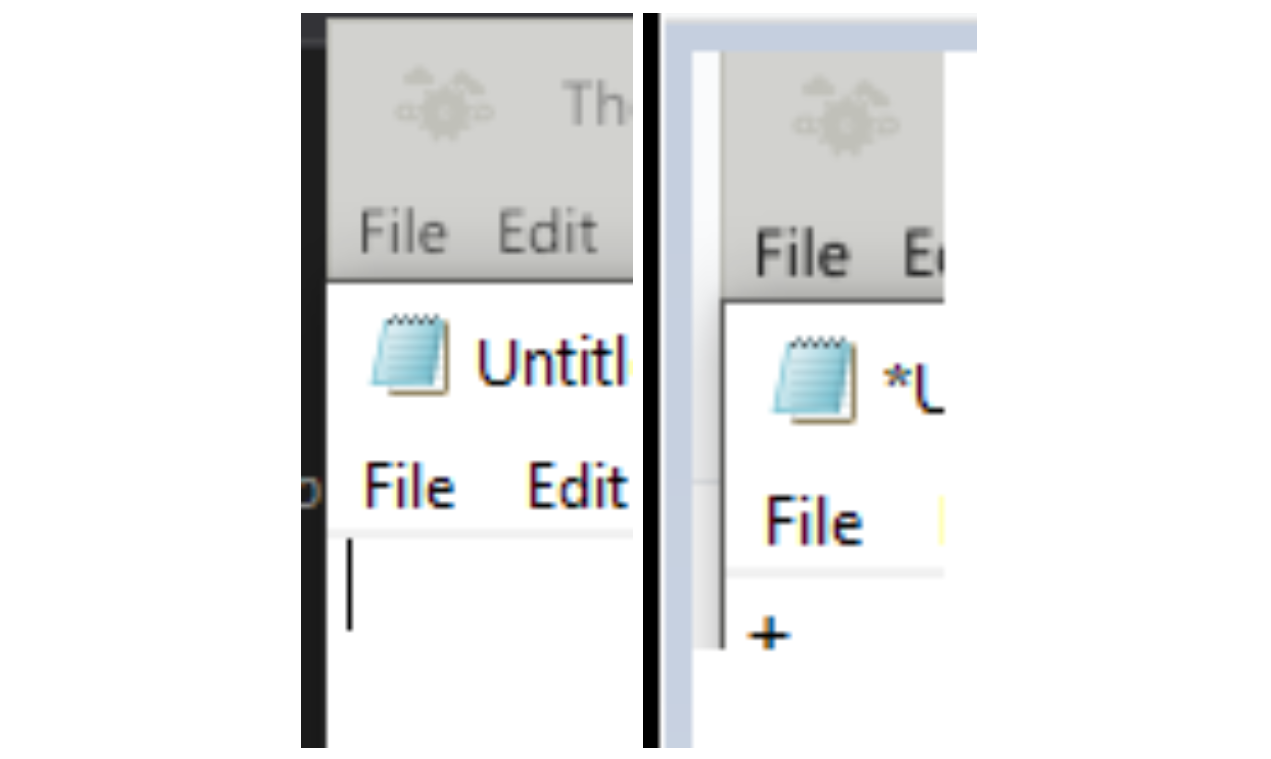
When we blend text “correctly” it doesn’t match what the user expects from using system software such as Notepad.
Precision isn’t great
The viewers in The Machinery are rendered differently than in the final application. In the final
application, we can just write to the swap chain and be done with it, but the editor is a bit
trickier. We instead render the viewers (scene tab, preview tab, etc.) to an intermediate texture
and then use that as an input for our GUI shader. This way, the editor GUI doesn’t have to know
about the viewers and will just treat them as textures. The problem is that the GUI shader (for
reasons discussed earlier) expects its colors to be in sRGB format instead of linear BT.709. This
means that if we want to use the default output_system we have to first convert from sRGB to
linear BT.709 only to convert back to sRGB if we’re rendering to LDR.
And the issue with that is that the transfer functions aren’t perfect since we’re working with limited precision floating-point numbers:
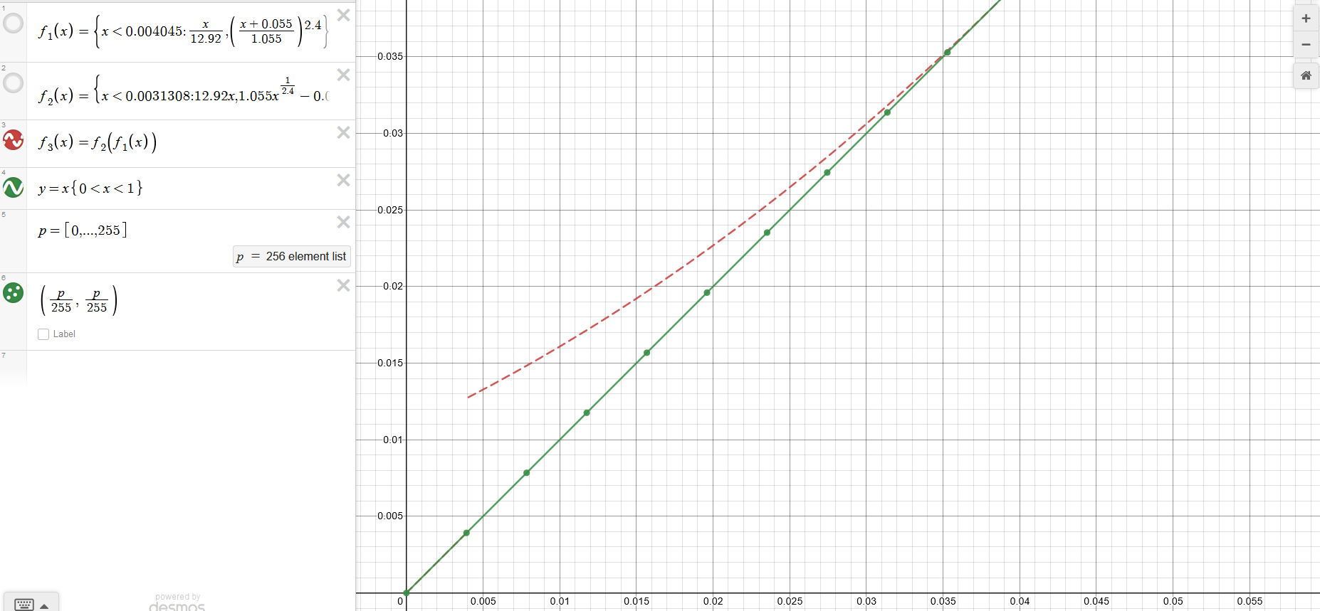
Limited precision causes issues when we apply the transfer function and its inverse.
In this graph, you can see the error if we convert from sRGB to linear and then back to sRGB. The
green line shows the expected output (with the green dots representing individual floating point
values assuming 8-bits), and the dotted red line shows the actual output. The subrange [2, 9] out of
the full [0, 255] range has errors. This is barely noticeable to the naked eye, but one of our unit
tests thankfully caught it. To solve this I added one more function to the output_system:
srgb_to_color_space(float3 color) . This function assumes that the input is in non-linear space
instead of linear space, allowing me to skip the double transfer function.
Assumptions galore
There are two assumptions that I want to briefly talk about that are important to know when implementing a system like this. The first one is simple, row-major vs column-major matrices.
We use 3x3 matrices to convert from one color primary into another, for example, to convert from BT.709 to BT.2020 we would use the following conversion (derivation):
We need to be careful not to blindly copy these matrices from an online source as most of them use row-major ordering. The Machinery (like many other engines) uses column-major matrices, so we need to transpose them before using them.
The second assumption lies in the ST2084 PQ transfer function. The function is defined as follows
The two values we’re concerned about here are F_D (which is our linear BT.2020 input color) and the 10,000 scalar value. This 10,000 is the maximum luminance (in NITS) of the PQ transfer function. If you would use this function directly and inspect the output you’d see that it’s mathematically correct, but the colors on the screen will look very washed out. Why is this?
It is because most monitors can’t actually display 10000 NITS (which would be about the same as a street light worth of brightness for every square meter of the monitor). My display can for instance only display an average of 350 NITS (I checked this with DisplayHDR test). Therefore we need to scale this function accordingly:
Testing and calibration
Checking by eyeballing it will only get you so far white unit tests can point out smaller inaccuracies that could otherwise go unnoticed. We currently have several unit tests in place for making sure these colors are correct. First, we make sure that the conversion matrices being generated are the ones we expect. This is being checked with the BT.709 matrices. Secondly, we have a GPU read back unit test that writes a constant value to various types of images, converts it, and then reads back the result. This test checks sRGB to sRGB and has caught several issues already.
But, in order to really test whether these colors are correct, we should calibrate our monitors and then measure the luminance produced by our application relative to the calibration software. Sadly, I don’t have a hardware calibrator and they are rather expensive, so I have not done this step yet.
Wrap up
Currently, The Machinery fully supports outputting to sRGB and HDR10 capable displays, but adding
additional color spaces has been made easier by this system. Only the output_sytem has to know
about what the actual output space is which makes it really easy to support HDR.
Color is a fascinating and very broad topic which I would like to get more into in the future. Possibly by adding additional tools for color grading and scene calibration using things like Macbeth charts and a vectorscope.