Linear Algebra Shenanigans: Gizmo Repair
This post will take you through the thought process of realizing something being wrong with our gizmos, going through the code, adding some debug drawing to help with the diagnosis, and what I did to fix it. Since it is such a narrow deep dive, source code for most non-trivial functions used is included, either in the text or as appendices.
Gizmos are the three-axes things in the editor viewport that let you move, rotate, and scale objects. One day I noticed something was off with our move gizmo. In the animation below you see me use it to move an object. Everything seems to work fine, including dragging while having the cursor away from the axis.
Moving an object viewed from the side, seems to work fine!
Now, if we instead of rotating the view so that the blue gizmo axis points down the screen at a steep angle and try again, the following happens:
Moving an object viewed at a steep camera angle, going off-axis makes it all bonkers!
As long as the cursor remains near the gizmo axis, everything is fine. But the user should be able to initiate a move operation by clicking the axis and, while holding the mouse button down, move away from the axis and still be able to drag the object as if the cursor was on the axis. This does not work properly, the object starts moving backward instead! I expect my cursor position to somehow project onto the axis which I used to initiate the move operation. A projection is just a fancy word for finding the point on a line or surface that is closest to some other point.
Let’s have a look at the code of the move gizmo. Here the code that initiates the move operation, i.e. the code that is run once when the user initially clicks on the gizmo:
const tm_vec3_t cursor[2] = {
    { mouse_pos.x, mouse_pos.y, 0 },
    { mouse_pos.x, mouse_pos.y, 1 }
};
tm_vec3_t cursor_world[2];
tm_camera_api->screen_to_world(camera, TM_CAMERA_TRANSFORM_DEFAULT, viewport, cursor, cursor_world, 2);
const tm_vec3_t cursor_pos = cursor_world[0];
const tm_vec3_t cursor_dir = tm_vec3_normalize(tm_vec3_sub(cursor_world[1], cursor_world[0]));
a->st = tm_line_line_intersection(a->world_pos, a->axis, cursor_pos, cursor_dir);
First, we get the world position of the cursor, this is done using our screen_to_world function
(Appendix A). We also get the world “direction” of the cursor. We
define this as the world-space vector that points into the screen at the cursor position. Finally,
we make a line-line “intersection” (Appendix B) between the
gizmo-axis line and the world-space cursor line. It’s not really an intersection; it finds the
points along the two lines at which the distance between the lines is minimal. The return value of
tm_line_line_intersection is a tm_vec2_t, where the x component is the minimizing point along
the axis line, and the y component is the point along the cursor line (actually, it’s not really
points, it’s the parameters s and t of the lines A + sU and B + tV). Again, this is just the
code that initiates the move operation, so we cache the result in a->st for later use.
During each subsequent frame (for as long as the mouse button is held) we do the following:
tm_vec2_t st = tm_line_line_intersection(a->world_pos, a->axis, cursor_pos, cursor_dir);
float ds = st.x - a->st.x;
const tm_vec3_t world_delta = tm_vec3_mul(a->axis, ds);
const tm_vec3_t local_delta = tm_quaternion_rotate_vec3(parent_rot_inv, world_delta);
local->pos = tm_vec3_add(a->local_pos, local_delta);
Here cursor_pos and cursor_dir are found as in the above, but now they change as the user moves
the mouse. Again, we get the line-line intersection, which in turn is used to calculate a “delta”
along the axis line by subtracting our starting position from the current position. This ds value
is then multiplied with the axis along which we are moving, a->axis. We then transform this
world_delta into coordinates local for the object and add the local_delta to the position of the
local transform.
That’s the gist of it. But what goes wrong? Let’s add some debug rendering right after the code above:
tm_vec3_t debug_draw[2];
debug_draw[0] = tm_vec3_add(cursor_pos, tm_vec3_mul(cursor_dir, st.y));
debug_draw[1] = tm_vec3_add(a->world_pos, tm_vec3_mul(a->axis, st.x));
tm_primitive_drawer_api->stroke_lines(pbuf, vbuf, tm_mat44_identity(), debug_draw, 1, (tm_color_srgb_t){ 255, 255, 255, 255 }, 2.0f);
This shows up as a white line with endpoints at the points which tm_line_line_intersection finds
as the points at which the two lines are at a minimum distance from each other:
Moving the object at a steep camera angle with a white debug line.
With the debug rendering we can see what goes wrong: As the user moves the cursor far away from the
axis, the closest point on the gizmo axis that tm_line_line_intersection finds gets closer and
closer to the screen as we move further from the axis.
At this point I realize the big error: We can’t just intersect these two lines, where one is a line that points into the screen at the cursor position. The whole concept of this world-space cursor line felt very fishy to me. Why are we putting the 2D cursor position into the 3D world, and giving it some arbitrary direction? How is that supposed to give us the closest point on the gizmo-axis line? At this point, I tried to come up with alternate solutions, such as using the vector from the cursor’s world position to the object’s current position as the “direction” of the cursor. I also thought of doing a 3D projection of the cursor’s world position onto the gizmo line. But what is a reasonable value for the cursor’s world position? It felt like I was missing a piece of information.
But then I thought, if it’s weird to take the 2D cursor position into the 3D space, what can I do instead? While thinking of how the imaginary gizmo-axis line goes across the screen it came to me: The screen! Pull the axis of the gizmo into screen space and project the mouse position onto that! Since I’m then in 2D-land, I don’t even need the weird “mouse direction” to figure out where on the gizmo line I am, I can just do the classic 2D point-on-line projection of the cursor position and the screen-space gizmo line! Below is an illustration of this. The pink line is the screen-space gizmo line and the light blue line shows us how the cursor should project onto the line:
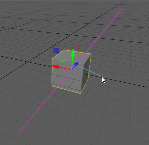
What we want instead: Bring the line of the gizmo axis into screen space and project the screen-space mouse position onto the screen-space gizmo line.
It’s funny that it took me a while to get this insight since I even thought of the earlier code as “doing a projection” of the cursor position onto a line. But it didn’t really, it just found the shortest distance between two 3D lines. The whole projection was missing!
Here’s the new code I cooked up, when we initiate the gizmo move operation we now do this:
a->axis_start_pos = private__gizmo_axis_intersection(a->world_pos, a->axis, (tm_vec2_t){ mouse_pos.x, mouse_pos.y }, camera, viewport).x;
Where private__gizmo_axis_intersection looks like this:
tm_vec2_t private__gizmo_axis_intersection(tm_vec3_t gizmo_world_pos, tm_vec3_t gizmo_axis, tm_vec2_t mouse_pos, const tm_camera_t *camera, tm_rect_t viewport)
{
    const tm_vec3_t gizmo_world[2] = { gizmo_world_pos, tm_vec3_add(gizmo_world_pos, gizmo_axis) };
    tm_vec3_t gizmo_screen[2];
    tm_camera_api->world_to_screen(camera, TM_CAMERA_TRANSFORM_DEFAULT, viewport, gizmo_world, gizmo_screen, 2);
    const tm_vec2_t gizmo_screen_pos = { gizmo_screen[0].x, gizmo_screen[0].y };
    const tm_vec2_t gizmo_screen_dir = { gizmo_screen[1].x - gizmo_screen_pos.x, gizmo_screen[1].y - gizmo_screen_pos.y };
    const tm_vec2_t mouse_on_gizmo = tm_point_on_line_projection_2d(gizmo_screen_pos, gizmo_screen_dir, mouse_pos);
    const tm_vec3_t mouse_on_gizmo_screen[2] = { { mouse_on_gizmo.x, mouse_on_gizmo.y, 0 }, { mouse_on_gizmo.x, mouse_on_gizmo.y, 1 } };
    tm_vec3_t mouse_on_gizmo_world[2];
    tm_camera_api->screen_to_world(camera, TM_CAMERA_TRANSFORM_DEFAULT, viewport, mouse_on_gizmo_screen, mouse_on_gizmo_world, 2);
    return tm_line_line_intersection(gizmo_world_pos, gizmo_axis, mouse_on_gizmo_world[0], tm_vec3_normalize(tm_vec3_sub(mouse_on_gizmo_world[1], mouse_on_gizmo_world[0])));
}
Here we use world_to_screen (Appendix C) instead of
screen_to_world to get the screen-space coordinates of two points on the gizmo line, we need two
points so we can construct a 2D line for the gizmo axis. This gives us gizmo_screen_pos and
gizmo_screen_dir. Now we use the aforementioned linear algebra classic:
tm_point_on_line_projection_2d (Appendix D). This
gives us the point mouse_on_gizmo: the screen-space point on the gizmo line that is closest to our
mouse cursor. Finally, we do sort of what the old code did: We use mouse_on_gizmo to create a
world-space line into the screen at that point, and we intersect it with the world-space gizmo line.
The difference is that a line pointing inward at mouse_on_gizmo will go right through the gizmo
axis, so none of the strangeness from before will happen.
For every frame we continue to hold the mouse button, we do this:
const tm_vec2_t st = private__gizmo_axis_intersection(a->world_pos, a->axis, (tm_vec2_t){ mouse_pos.x, mouse_pos.y }, camera, viewport);
float ds = st.x - a->axis_start_pos;
tm_vec3_t world_delta = tm_vec3_mul(a->axis, ds);
const tm_vec3_t local_delta = tm_quaternion_rotate_vec3(parent_rot_inv, world_delta);
local->pos = tm_vec3_add(a->local_pos, local_delta);
Here we run the same function, private__gizmo_axis_intersection again, but feeding it the current
mouse position. We can then calculate a delta, ds, along the line and find the world delta along
the axis, transform it into local space, and then add it to the local transform’s position.
Does it work? Yes:
The result of the new code, with added debug lines analogous to how the earlier illustration looked.
Again, I’ve put in some debug lines to illustrate what’s going on (also, it’s fun to add debugging
graphics that makes it look like your sketches), for completeness, here’s the debug drawing code I
added to private__gizmo_axis_intersection:
style->line_width = 2.0f;
style->color = (tm_color_srgb_t){230, 48, 218, 255};
tm_draw2d_api->stroke_polyline(uib.vbuffer, uib.ibuffers[TM_UI_BUFFER_MAIN], style, (tm_vec2_t[2]){ tm_vec2_add(gizmo_screen_pos, tm_vec2_mul(gizmo_screen_dir, -1000.0f)), tm_vec2_add(gizmo_screen_pos, tm_vec2_mul(gizmo_screen_dir, 1000.0f)) }, 2, false);
style->color = (tm_color_srgb_t){47, 206, 230, 255};
tm_draw2d_api->stroke_polyline(uib.vbuffer, uib.ibuffers[TM_UI_BUFFER_MAIN], style, (tm_vec2_t[2]){ mouse_pos, mouse_on_gizmo }, 2, false);
This time we use tm_draw2d_api since we are drawing screen space lines.
Conclusion
After fixing the move gizmo, I realized that the scale gizmo had similar problems. I could then fix
it quickly by reusing private__gizmo_axis_intersection to fix both the single-axis scale as well
as the two-axis scale.
It’s always a good idea to question the code that is already there, especially if it does something rather strange. It can be hard to question code that you haven’t written yourself, maybe you’re thinking that the person who wrote this surely knew what they were doing, it must just be a tiny bug somewhere! So you sit there and wrestle with the current code. But no, we all make mistakes, and I think it’s an important insight for every programmer to have: that everyone, not just junior people, makes mistakes, sometimes big ones!
It’s when we sit down and really think something through, draw some sketches and really get our head into the problem we can start feeling sure about what may be wrong and what we’re doing, otherwise, I feel that I’m merely guessing.
Appendix A: screen_to_world
// Does the opposite of world to screen -- i.e. converts from screen coordinates back to world
// coordinates. Returns a pointer to the `world` array.
// Note: `screen.z` should is clip space Z with near plane mapped to 0.f and far plane at 1.f regardless
// if engine is setup to run with reversed Z or not.
tm_vec3_t *screen_to_world(const tm_camera_t *camera, tm_camera_transform transform, tm_rect_t viewport, const tm_vec3_t *screen, tm_vec3_t *world, uint32_t n)
{
    tm_mat44_t view_inv, proj_inv;
    tm_mat44_inverse(&view_inv, &camera->view[transform]);
    tm_mat44_inverse(&proj_inv, &camera->projection[transform]);

    tm_vec3_t *w = world;
    const tm_vec3_t *s = screen;
    for (uint32_t i = 0; i < n; ++i, ++w, ++s) {
        tm_vec4_t p = { 0, 0, 0, 1 };
#if defined(TM_PROJECTION_USE_REVERSED_Z)
        p.z = 1.f - s->z;
#else
        p.z = s->z;
#endif
        p.y = 1 - 2 * (s->y - viewport.y) / viewport.h;
        p.x = 2 * (s->x - viewport.x) / viewport.w - 1;
        tm_vec4_t unprojected = tm_mat44_transform_vec4(&proj_inv, p);
        tm_vec4_t w4 = tm_mat44_transform_vec4(&view_inv, unprojected);
        w->x = w4.x / w4.w;
        w->y = w4.y / w4.w;
        w->z = w4.z / w4.w;
    }
    return world;
}
Appendix B: tm_line_line_intersection
// Finds the parameters (s,t) that minimizes the distance between A + sU and B + tV. If the lines
// are parallel, the function returns {0,0}.
tm_vec2_t tm_line_line_intersection(tm_vec3_t a, tm_vec3_t u, tm_vec3_t b, tm_vec3_t v)
{
    const float au = tm_vec3_dot(a, u), av = tm_vec3_dot(a, v), bu = tm_vec3_dot(b, u), bv = tm_vec3_dot(b, v), uv = tm_vec3_dot(u, v);
    if (uv * uv > 1 - 1e-5f) {
        const tm_vec2_t res = { 0, 0 };
        return res;
    }
    const float s = (bu + av * uv - bv * uv - au) / (1 - uv * uv);
    const float t = (av + bu * uv - au * uv - bv) / (1 - uv * uv);
    const tm_vec2_t res = { s, t };
    return res;
}
Appendix C: world_to_screen
// Converts from world coordinates to screen coordinates as seen by a camera. `transform`
// specifies which view and projection transform to use. Returns a pointer to the `screen`
// array.
// Note: `screen.z` is clip space Z with near plane at 0.f and far plane at 1.f regardless
// if engine is setup to run with reversed Z or not.
tm_vec3_t *world_to_screen(const tm_camera_t *camera, tm_camera_transform transform, tm_rect_t viewport, const tm_vec3_t *world, tm_vec3_t *screen, uint32_t n)
{
    const tm_mat44_t view = camera->view[transform];
    const tm_mat44_t proj = camera->projection[transform];

    const tm_vec3_t *w = world;
    tm_vec3_t *s = screen;
    for (uint32_t i = 0; i < n; ++i, ++w, ++s) {
        const tm_vec4_t unprojected = tm_mat44_transform_vec4(&view, (tm_vec4_t){ w->x, w->y, w->z, 1.0f });
        tm_vec4_t p = tm_mat44_transform_vec4(&proj, unprojected);
        const float wabs = fabsf(p.w);
        p.x /= wabs, p.y /= wabs, p.z /= wabs;
        s->x = viewport.x + (0.5f + p.x / 2) * viewport.w;
        s->y = viewport.y + (0.5f - p.y / 2) * viewport.h;
#if defined(TM_PROJECTION_USE_REVERSED_Z)
        s->z = 1.f - p.z;
#else
        s->z = p.z;
#endif
    }
    return screen;
}
Appendix D: tm_point_on_line_projection_2d
// Projects the point `p` onto the line `A + tU`.
tm_vec2_t tm_point_on_line_projection_2d(tm_vec2_t a, tm_vec2_t u, tm_vec2_t p)
{
    const float uu = tm_vec2_dot(u, u);

    // The direction is very short, return the line origin;
    if (uu < 0.00001f)
        return a;

    return tm_vec2_add(a, tm_vec2_mul(u, (tm_vec2_dot(u, tm_vec2_sub(p, a)) / uu)));
}